Steps for simulating VHDL programs in OrCAD

  1. Go to Start --> Programs -->OrCAD Release 9.1 -->Capture CIS

     
  2. Go to File -->New -->Project...
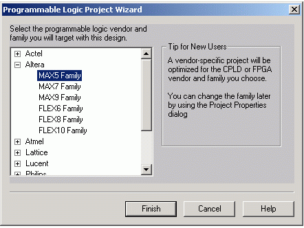
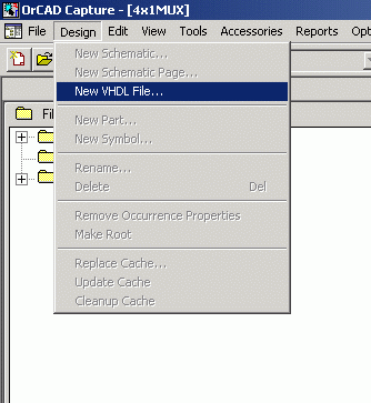
    Select Programmable Logic Wizard
    Give a suitable name and location for your project.
     
  3. Select any vendor or family as right now you are not concerned with programming it.
    Click on Finish.


  4. You will reach the project window:


  5. Now click on Design -->New VHDL file


  6. You will get a message:

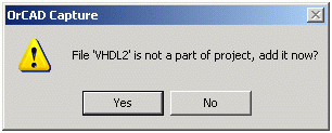
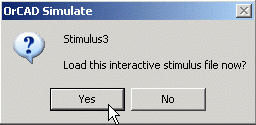
    Click on Yes to add the file to your project.

     
  7. Save your VHDL file, preferably in the same folder you created the project in. Give it a suitable name.


  8. In the Editor window, write down your VHDL program.


  9. Now minimize the Editor, and go to the Project window. (You can also do this via the Window menu)


  10. Now click on Tools  Compile…


  11. Accept the defaults and click on Ok to compile.


  12. In case you get an error message, correct your VHDL file (restore it) and repeat steps 10 & 11.
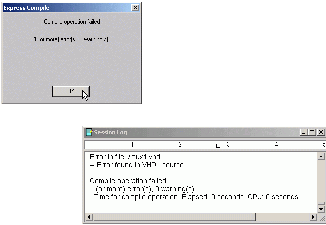
    The session log helps you to determine the line numbers which have errors in them.

     
  13. Now click on Tools -->Simulate…

     
  14. Select In Design and Click on Ok.


  15. Click on Yes to load the circuit.


  16. Now to set up the inputs, go to Stimulus  New Interactive…


  17. Here you set up inputs to your circuit. It has three main options:
     
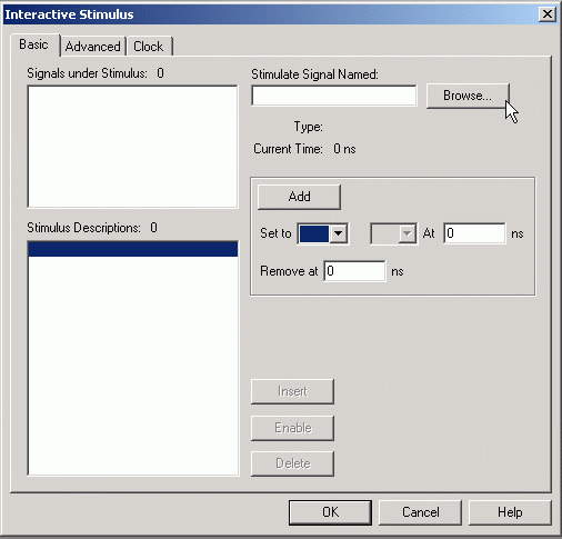
    1. Basic: Here you can give constant values to the input for/at specified time intervals. For e.g. 0 for 5ns, 1 from 5ns to 10ns…
    2. Clock: When you want to give a clock signal or if you want to give all possible input combinations like in a truth table (e.g. 00, 01, 10, 11 …).
    3. Advanced: Here you have advanced stimulus options. We do not usually use this.

    Note that if you change stimulus after running the simulation once, you must go to Simulate  Restart in order to bring back the starting time to 0. Otherwise, you may get wrong results.


  18. For Basic stimulus, click on Browse and select an appropriate input signal, then set its values and then click on Add. Repeat for all inputs.


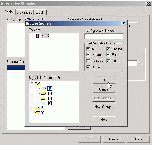
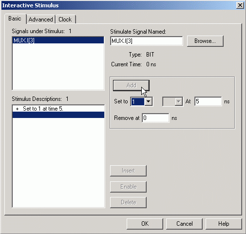
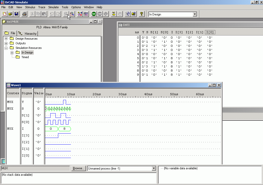
    We have selected input I3 of the MUX.

    We set it up to become 1 at 5 ns.

     
  19. When you need to give a lot of input combinations, Clock is very useful. For e.g. you want to give the inputs 00, 01, 10 and 11 to the MUX select lines S0 and S1 automatically. Basically you are producing a complete truth table here, with all the entries…

    Browse for the Least Significant Bit first, S0 in this case. Set it up as shown below. Set to 0 for 1ns and Set to 1 for 1ns.


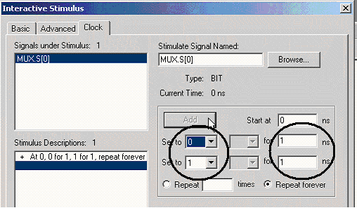
    Now select the next higher order bit S1, but this time, double the time to 2ns.

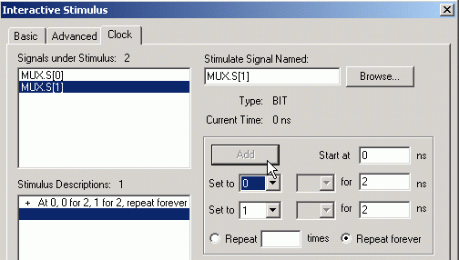
    Had there been another input S2, you would have given it 0 for 4ns 1 for 4ns (double of 2ns) and so on.

     
  20. Now click on Ok. Say Yes to load the interactive stimulus file.

     
  21. Now you have to run your simulation to se the results. Click on Simulate -->Run...


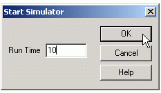
    Select a suitable time limit. (Roughly to accommodate one truth table, here 4 would have sufficed). Click on Ok to run it.


  22. You will get the output as a waveform and observation table.
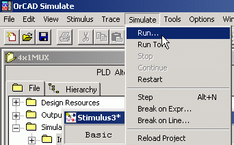
    You may have to click on to zoom in on the waveform.

     
  23. When you close the Simulate program, you are recommended to save and add the stimulus to your project, so that the next time you run it you don’t have to enter the stimulus again.


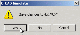
    When you close OrCAD, click on Yes to save the stimulus with your project.


Bye.